
MeArm sur le Raspberry Pi
Faire fonctionner un MeArm sur un Raspberry Pi est initialement très simple. Nous espérons le rendre encore plus simple avec de bons exemples de code. Actuellement, il est très facile de le mettre en marche avec seulement quelques câbles de raccordement et une alimentation externe (comme notre alimentation 6V 2A).

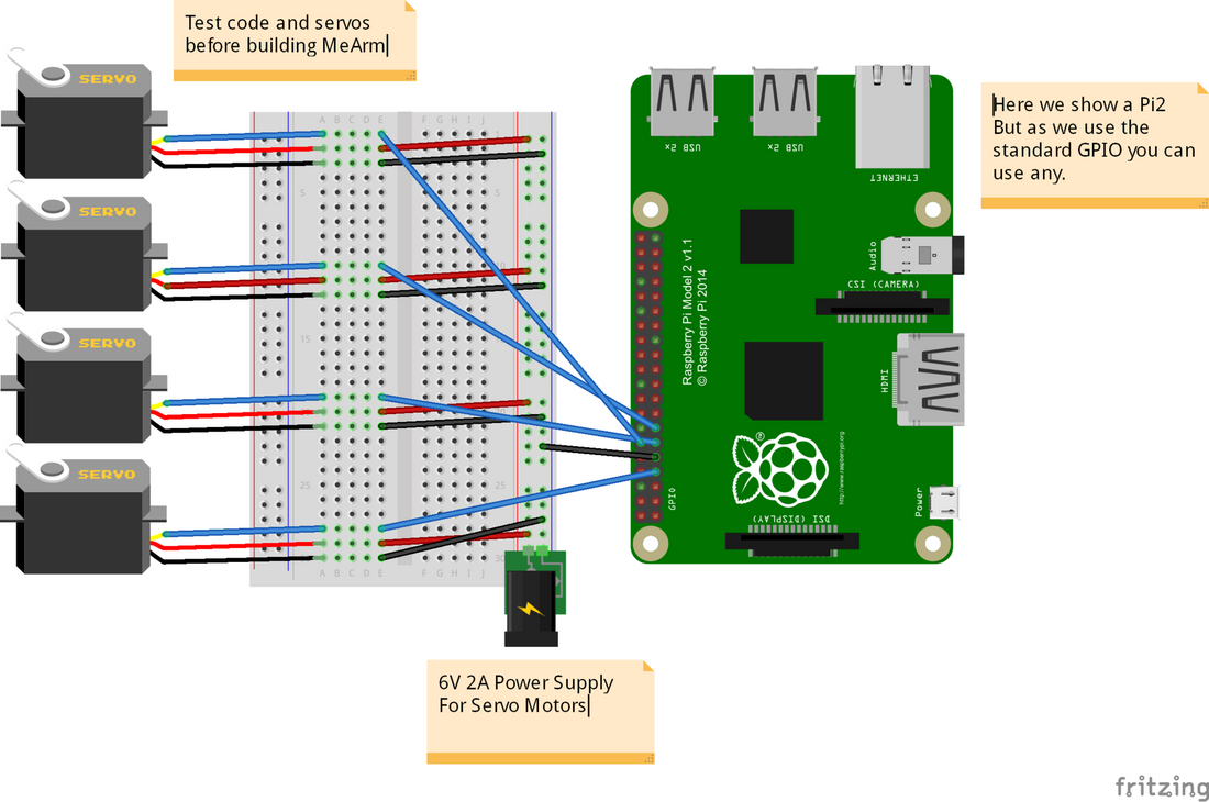
Nous partons du principe que vous avez un Raspberry Pi fonctionnel et tous les accessoires nécessaires pour cela. Une fois qu'il est en marche, vous devrez connecter le Pi aux servomoteurs comme indiqué ci-dessous. Nous utilisons les GPIO 4, 17, 18 et 27. Ceux-ci deviendront respectivement les servomoteurs 0, 1, 2 et 3. Nous vous recommandons d'effectuer tout ce processus avant de construire votre MeArm afin de gagner du temps lors de l'étalonnage et d'éviter de griller vos servomoteurs en les envoyant là où ils ne peuvent pas aller ! (fichier disponible ici)

La platine d'expérimentation utilisée dans l'image est juste pour rendre les choses plus ordonnées. En réalité, vous pouvez simplement connecter toutes les masses et toutes les lignes d'alimentation et les câbler directement à l'alimentation, puis amener les lignes PWM (les fils de commande du servomoteur qui proviennent du GPIO) directement aux servomoteurs. Ne connectez pas l'alimentation 6V au GPIO (sauf le fil de masse). De plus, il n'est pas conseillé de tirer l'alimentation des servomoteurs via le GPIO, ils peuvent tirer jusqu'à un ampère chacun et le Pi n'est pas configuré pour cela. Mieux vaut prévenir que d'avoir à acheter un nouveau Pi !
Maintenant, nous devrons accéder à la ligne de commande sur votre Pi. Soit vous démarrez dessus, soit vous utilisez un terminal dans votre interface graphique. Nous avons utilisé une nouvelle installation de Raspian.
|
pi@raspberry ~ $ git clone git://github.com/richardghirst/PiBits.git pi@raspberry ~ $ cd PiBits/ServoBlaster/user pi@raspberry ~/PiBits/ServoBlaster/user $ sudo ./servod --idle-timeout=2000 Board revision: 2 Using P1 pins: 7,11,12,13,15,16,18,22 Servo mapping: |
Maintenant, si tout fonctionne correctement, vous pourrez envoyer la commande
| pi@raspberry ~/PiBits/ServoBlaster/user $ echo 0=50% > /dev/servoblaster |
Ceci enverra le servomoteur 0 (celui connecté au GPIO 4) à 50% de sa course. Changer pour echo 1=20% > /dev/servoblaster enverra le servomoteur 1 à 20% de sa course de 0 à 180 degrés.
Ensuite, nous utilisons Python et quelque chose appelé TKinter (qui devrait déjà être installé sur votre Pi). Créez un nouveau fichier en utilisant votre éditeur de fichiers préféré (ce devrait être GVIM - cela vous rendra plus populaire, plus fort et plus beau). Je l'ai appelé MeArm.py. Ajoutez le code suivant et enregistrez.
| #!/usr/bin/env python from Tkinter import * #allows us to make a GUI with TKinter import os root = Tk() # First Set Up the Servos # Going to use lists for this SNums = [0,1,2,3] #Numbers of the Servos we'll be using in ServoBlaster SName = ["Waist","Left","Right","Claw"] #Names of Servos AInis = [90,152,90,60] #Initial angle for Servos 0-3 AMins = [0,60,40,60] #Minimum angles for Servos 0-3 AMaxs = [180,165,180,180] #Maximum angles for Servos 0-3 ACurs = AInis #Current angles being set as the intial angles Step = 5 for i in range(4): print(SNums[i],AInis[i],AMins[i],AMaxs[i],ACurs[i]) os.system('sudo /home/pi/PiBits/ServoBlaster/user/servod --idle-timeout=2000') #This line is sent to command line to start the servo controller #inc listens for all key presses. On certain presses in the if statements below it either calls a process to add or subtract from the current servo angle. def inc(event): print "pressed", repr(event.char) if repr(event.char) == "'a'": AAdd(0) if repr(event.char) == "'d'": ASub(0) if repr(event.char) == "'w'": AAdd(1) if repr(event.char) == "'s'": ASub(1) if repr(event.char) == "'j'": AAdd(2) if repr(event.char) == "'l'": ASub(2) if repr(event.char) == "'i'": AAdd(3) if repr(event.char) == "'k'": ASub(3) def callback(event): frame.focus_set() def AAdd(Servo): if ACurs[Servo] < AMaxs[Servo]: ACurs[Servo] = ACurs[Servo]+Step # micro = (1000 + (ACurs[Servo] * 5.555)) micro = (1000 + (ACurs[Servo] * 8.3333)) print(ACurs[Servo],micro) os.system("echo %d=%dus > /dev/servoblaster" % (SNums[Servo],micro)) else: print "Max Angle Reached",SName[Servo],"Servo" def ASub(Servo): if ACurs[Servo] > AMins[Servo]: ACurs[Servo] = ACurs[Servo]-Step # micro = (1000 + (ACurs[Servo] * 5.555)) micro = (1000 + (ACurs[Servo] * 8.3333)) print(ACurs[Servo],micro) os.system("echo %d=%dus > /dev/servoblaster" % (SNums[Servo],micro)) else: print "Min Angle Reached",SName[Servo],"Servo" frame = Frame(root, width=500, height=300) boxtext = Label(root, text="Click this box for keyboard command of the MeArm. Use the a d s w j l i and k keys for control.") boxtext.pack() frame.bind("<Key>",inc) frame.bind("<Button-1>", callback) frame.pack() root.mainloop() |
En utilisant un terminal ou la ligne de commande, tapez
| pi@raspberry ~ $ python MeArm.py |
Si tout se passe bien, une boîte de dialogue devrait apparaître vous invitant à cliquer à l'intérieur pour contrôler votre MeArm !
Voici une vidéo rapide et prête des résultats !
Ce tutoriel est rendu possible grâce à Carl Monk, qui l'a réalisé il y a près d'un an et est allé plus loin que moi ici. Son excellent travail peut être trouvé ici.
Nous nous basons tous deux sur le logiciel ServoBlaster de Richard Hirst et sur cet excellent article de Cihat Keser pour le faire fonctionner rapidement.
6 commentaires
I got to issuing the command “echo 0=50% > /dev/servoblast” and did not see the servo movement. I double-checked the connections of power (5V DC power supply), GND and orange to GPIO4. I also have verified with an oscilloscope to see the pulses from GPIO4 and power/ground to servo connector. Tests each of the 4 servos of the MeArm and they do not move. Any suggestion? Thanks.
Your website has clear instructions for building the mearm deluxe or with Arduino. I want to build it for use with RasberryPi and your instructions for that are vague!
The wires in your calibration picture are the wrong colours and don’t have suitable ends for a breadboard.
The code required is very unclear for a non-python expert. There seems to be a lot of non-code in amongst the code so it is unclear what I need to code in python to calibrate the servos.
Then unlike the other two build instructions – there is no instruction on actually building the robot! Although I guess I can look at one of the other two for that!
Help!
nick
Also, is the python TKinter file duplicated? It looks like it starts again half way down!
The git repository for PiBits has an incorrect URL on this page – it’s richardghirst, not richardghisrt
Tiny type on the repo name:
git://github.com/richardghisrt/PiBits.git
Should be:
git://github.com/richardghirst/PiBits.git
Many thanks, keen to try the Servo Blaster, I didn’t know that it would be able to control servos well enough.